
Two transistor analogy of SCR: if you are finding the two transistor model of SCR and want to know in detail, read this article completely for more information. SCR is also called as the thyristor so if you are finding the two transistor model of thyristor then also you are at right place.
What is SCR?
SCR (silicon controlled rectifier) is three terminal semiconductor switching device. Scr also names a thyristor. Construction of thyristor is like a pnpn transistor. It acts as the true switching in electronics. It can also convert alternating current into direct current and also control the power to the load. So thyristor is combined features of rectifier and transistor.
What is the two transistor analogy of SCR?
Two transistor analogy of SCR is a method of representing SCR in the form of two transistor model. This represents SCR is the combination of PNP and NPN transistor.
SCR or thyristor is a three terminal semiconductor device which having P-N-P-N structure. The basic operating principle of SCR can understand by two transistor method of SCR.
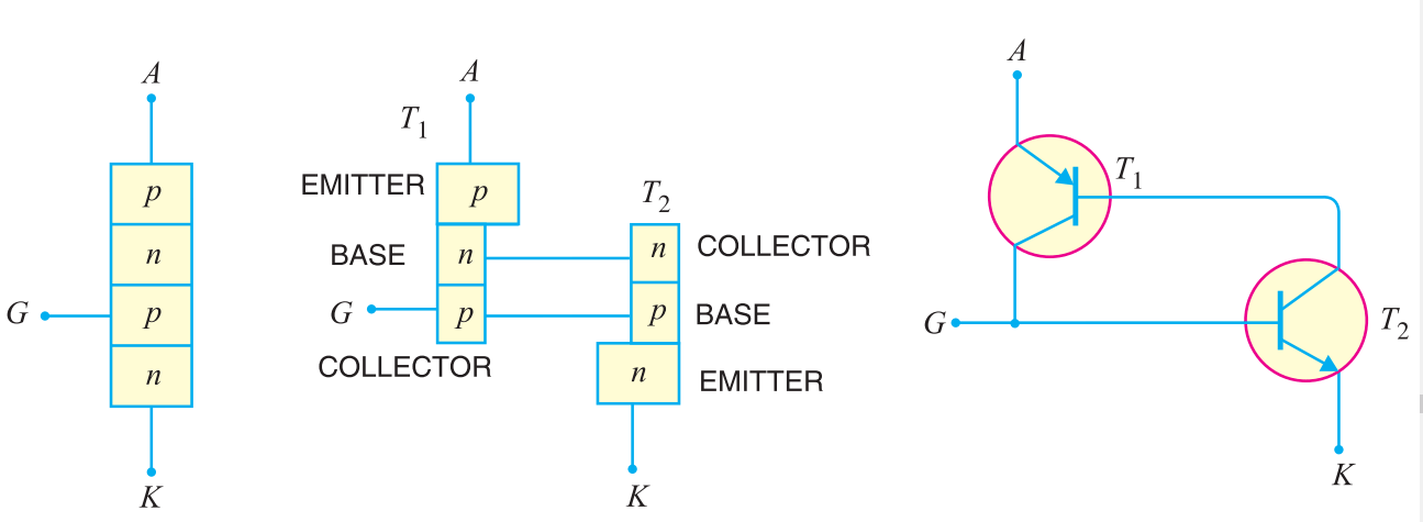
As per figure you can see two transistors equivalent circuit of SCR. From the figure, you can see the base of the transistor T1 is work as the collector of the transistor T2 and collector of the transistor T1 work as the base of the transistor T2.
Now here we find the expression for anode current of SCR.
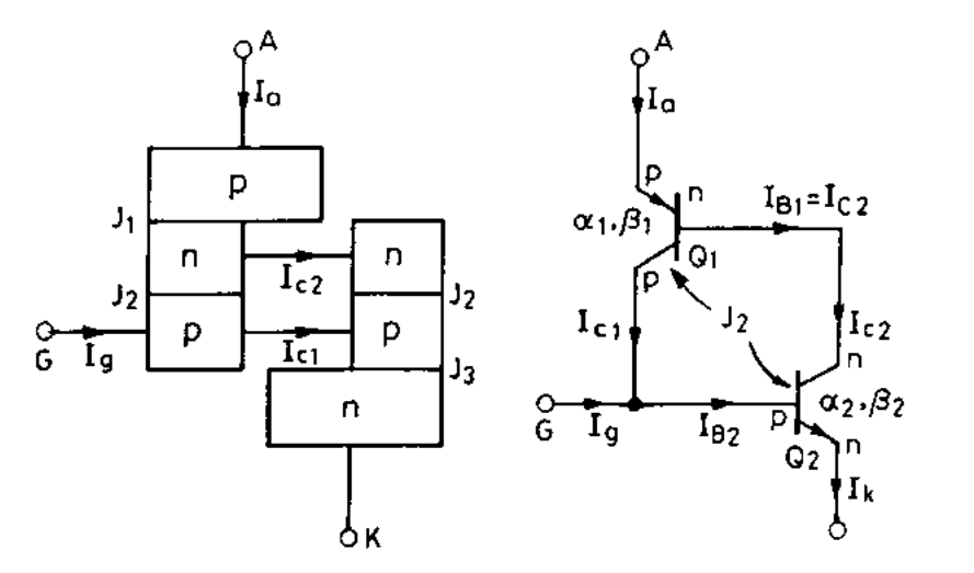
As per transistor leakage current equation,
Collector current is expressed as,
![]()
Where α is the current gain of transistor and Icbo is the leakage current of the common base transistor.
For transistor T1 emitter current = anode current Ia and collector current Ic = Ic1
![]()
Where α1 is the current gain of transistor T1.
Similarly, for transistor T2
![]()
Where α2 is the current gain of transistor T2. And emitter current of transistor T2 = cathode current Ik.
Hereby figure, you can see anode current Ia is the sum of two collector current: Ic1 and Ic2.
![]()
By putting Ik = Ia + Ig, anode current Ia will be,
![]()
SCR working with two transistor model
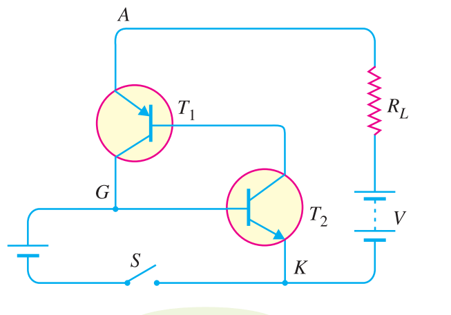
Woking of the SCR can be easily explained by two transistor model of SCR. As per figure you can see with supply voltage V and load resistance R is applied to SCR. Here first Assume the supply voltage V is less than break over voltage as is usually the case. When the gate is open (i.e. switch S open), there is base current Ib=0. For the base of the T2 is connected with the collector of The T1. Therefore, no current flows in the collector of T2 and hence that of T1. So for this condition, SCR is in OFF condition.
Whenever switch S is closed, a small gate current will flow through the base of T2 which means its collector current will increase. The collector of the transistor T2 is connected with transistor T1. So, the collector current of T2 is the base current of T1. Therefore, the collector current of T1 increases. But collector current of T1 is the base current of T2. This action is accumulative since an increase of current in one transistor causes an increase of current in the other transistor. As a result of this action, both transistors are driven to saturation, and heavy current flows through the load RL. Under such conditions, the SCR closes.
Characteristics of SCR:
It is a curve between anode-cathode voltage and anode current Ia at a constant gate voltage (Vg). The figure shows the characteristics of SCR.
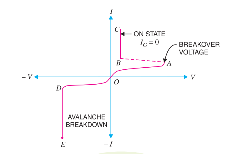
Forward characteristics: When a node is positive with respect to cathode curve between V and I at constant gate voltage called forward characteristics. When the supply voltage is increased from 0, at point A, SCR starts flowing current through it. At point A voltages when SCR conduct is called breakdown voltage. After breakdown voltage, voltage suddenly drops and nearly equal to the voltage across the load. Value of breakdown voltage is change with the constant gate voltage. With the proper gate voltage, we can get breakdown voltage at a small voltage.
Reverse characteristics: when the anode is negative with respect to cathode curve between V and I at constant gate voltage called reverse characteristics. A maximum reverse voltage at which SCR start conducting is called reverse breakdown voltage. You can see the reverse characteristics of SCR in the figure.
Conclusion:
Hope you understand all related to two transistor analogy of SCR. Scr can be represented in two transistors ( pnp and npn transistor). With the two transistor model of SCR working principle can easily understand. If you have any doubt related to this article kindly comment below. Thank you for your support..