Essentials of Transistor Oscillators
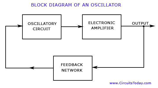
An oscillator must have the following three elements
- Oscillatory circuit or element.
- Amplifier.
- Feedback network.
The oscillatory circuit or element, also called the tank circuit, consists of an inductive coil of inductance L connected in parallel with a capacitor of capacitance C. The frequency of oscillation in the circuit depends upon the values of L and C. The actual frequency of oscillation is the resonant or natural frequency and is given by the expression
f = 1 / 2∏√LC Hz , where L is inductance of coil in henrys, and C is the capacitance of capacitor in farads.
The electronic amplifier receives dc power from the battery or dc power supply and converts it into ac power for supply to the tank circuit. The oscillations occurring in the tank circuit are applied to the input of the electronic amplifier. Because of the amplifying properties of the amplifier, we get increased output of these oscillations. This amplified output of oscillations is because of dc power supplied from the external source (a battery or power supply). The output of the amplifier can be supplied to the tank circuit to meet the losses.
The feedback network supplies a part of output power to the tank or oscillatory circuit in correct phase to aid the oscillations. In other words the feedback circuit provides positive feedback.

Types of Transistor Oscillators:
A transistor can be operated as an oscillator for producing continuous undamped oscillations of any desired frequency if tank (or oscillatory) and feedback circuits are property connected to it. All oscillators under different names have similar function i.e. they generate continuous undamped output. However, they differ in methods of supplying energy to the tank or oscillatory circuit to meet the losses and the frequency ranges over which they are used. (The frequency spectrum over which oscillators are employed to produce sinusoidal signals is extremely wide (from less than 1 Hz to many GHz)) However, no single oscillator design is practical for generating signals over this entire range. Instead, a variety of designs are employed, each of which generates sinusoidal outputs most advantageously over various portions of the frequency spectrum. Oscillators, which use inductance-capacitance (L-C) circuits as their tank or oscillatory circuits, are very popular for generating high-frequency (e.g. 10 kHz to 100 MHz) outputs.
The most widely used LC oscillators are the Hartley and Colpitt’s oscillators. Although they slightly differ from one another in their electronic circuitry but they have virtually identical frequency ranges and frequency stability characteristics. However, such oscillators are not suitable for generating low-frequency sinusoidal outputs. This is due to the fact that some components needed in construction of low-frequency LC resonant circuits are too bulky and heavy. So resistor-capacitor (R-C) oscillators are generally employed for generating low-frequency (from l Hz to about 1 MHz) sinusoidal signals.
Two most common R-C oscillators are the Wien bridge arid phase-shift types. Other less frequently used oscillators are the crystal oscillators and the negative resistance oscillators. The operating frequency ranges of various types of most commonly used oscillators are given below :Approximate
Type of Oscillator Frequency Ranges
Wien bridge oscillator 1 Hz — 1 MHz Phase shift oscillator 1 Hz — 10 MHz Hartley oscillator 10 kHz — 100 MHz Colpitt’s oscillator 10 kHz — 100 MHz Negative resistance oscillator > 100 MHz Crystal oscillator Fixed frequency
The oscillators of various types will be discussed in the following Articles.